
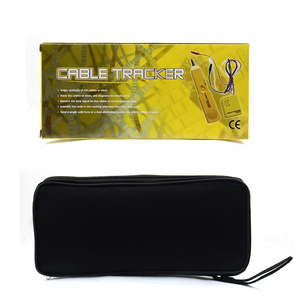
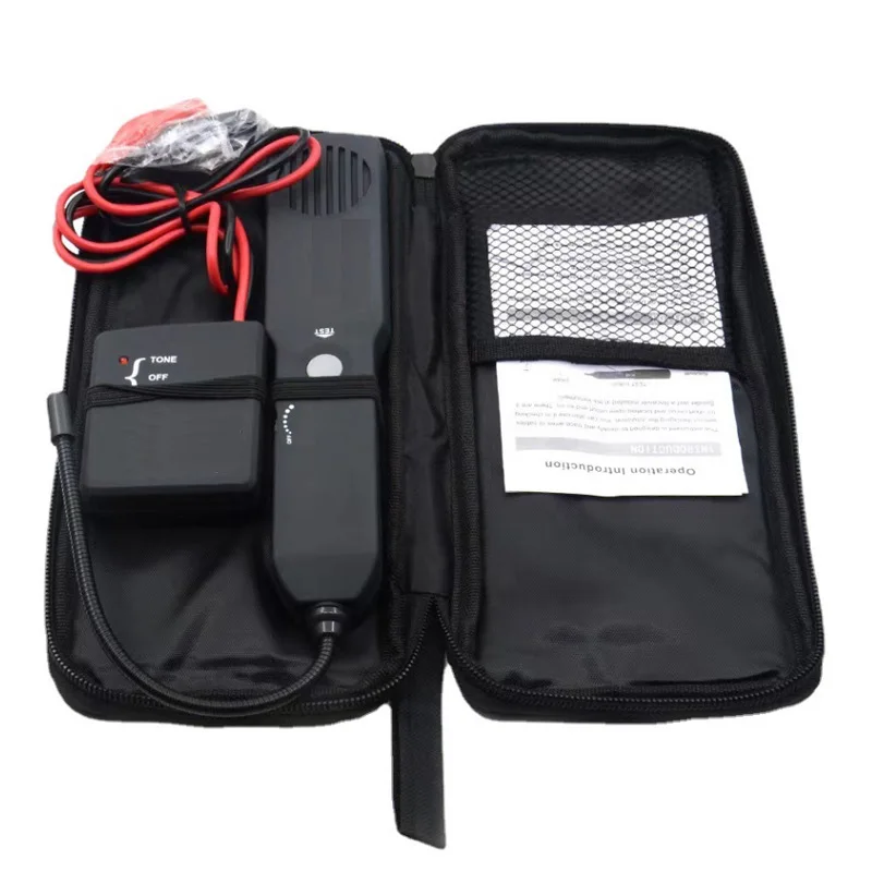
EM415PRO Automotive Short and Open Circuit Finder
The EM415PRO Automotive Circuit Tracer is a professional electrical diagnostic tool designed to trace vehicle wiring and help locate short circuits, open circuits and broken wires without piercing or damaging the cable insulation.
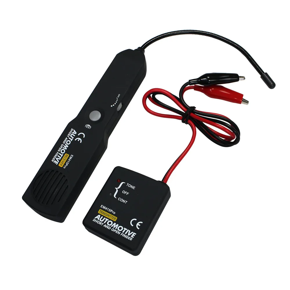
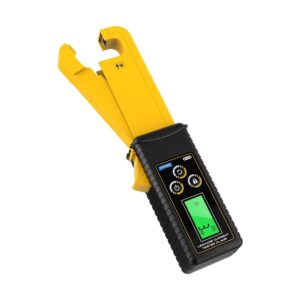
The kit consists of a signal transmitter and a handheld receiver. The transmitter applies a tracing signal to the selected wire, while the receiver follows that signal along the wiring harness using a flexible non-contact probe and adjustable sensitivity.
Main Features
- Traces automotive wires and cables
- Helps locate short circuits
- Helps locate open or broken circuits
- Identifies a specific wire inside a wiring harness
- Follows concealed cable routes
- Works without piercing the wire insulation
- Includes separate transmitter and receiver
- Adjustable receiver sensitivity
- Audible signal indication
- Flexible receiver probe for difficult areas
- Continuity-checking mode
- Suitable for low-voltage DC automotive circuits
- Works on DC circuits up to 42V
- Compact and portable carrying pouch
- Suitable for automotive electrical repair
Wire Tracing
The EM415PRO allows technicians to follow a selected wire through a vehicle wiring harness without removing all the insulation or disconnecting the complete harness.
After connecting the transmitter to the target circuit, move the receiver probe along the suspected cable route. The audible signal becomes stronger when the probe approaches the correct wire.
This function can be useful when tracing wires:
- Behind dashboards
- Under carpets
- Inside door panels
- Through engine compartments
- Along wiring harnesses
- Near fuse and relay boxes
- Inside crowded cable bundles
Short-Circuit Detection
The tool can help locate the position where a wire is shorted to ground or another conductor.
The transmitter sends a signal through the circuit, and the receiver follows the signal along the wire. A sudden loss or significant change in the received signal can help identify the area where the short circuit is located.
Final confirmation should be performed using a multimeter and the correct vehicle wiring diagram.
Open-Circuit Detection
The EM415PRO can also help locate broken or disconnected sections of wiring.
Follow the cable route using the receiver. When the audible signal disappears or drops significantly, inspect that area for:
- Broken conductors
- Damaged wiring
- Loose terminals
- Corroded connectors
- Disconnected plugs
- Failed splices
- Burned wiring
- Previous incorrect repairs
Wire Identification
When several similar wires are grouped together, the device can help identify the correct conductor.
Connect the transmitter to one end of the required wire and use the receiver to check the wires at the other end or within the harness. The target conductor will produce the strongest audible signal.
Non-Contact Cable Tracking
The receiver detects the signal without making direct electrical contact with the copper conductor. This allows the technician to trace wiring without cutting or piercing the insulation.
Avoiding unnecessary insulation damage helps protect the wiring from future corrosion, moisture and electrical faults.
Flexible Receiver Probe
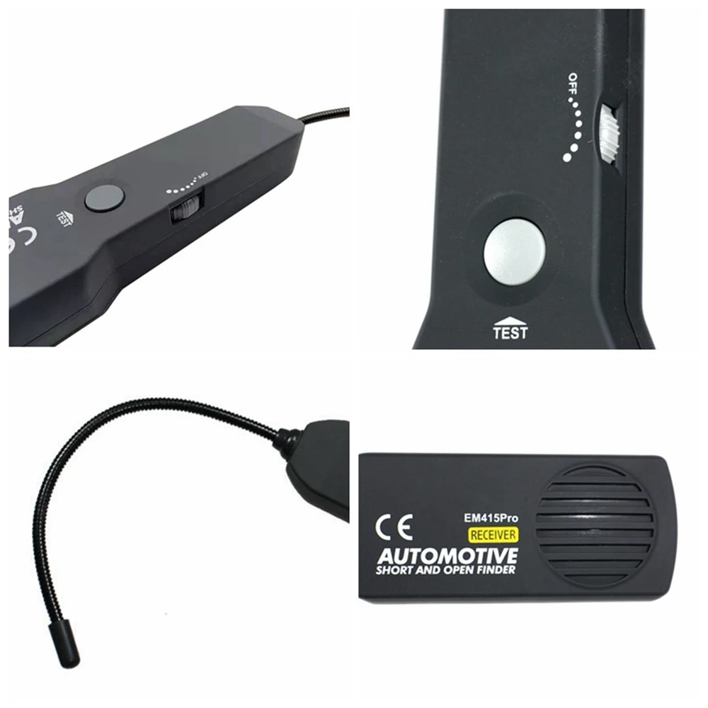
The receiver features a flexible coiled-steel probe that can be bent to reach wires in narrow or crowded areas.
For the best detection range, position the receiver probe tip approximately perpendicular to the wire being traced.
Adjustable Sensitivity
The receiver includes a sensitivity control that allows the technician to adjust signal detection according to the working environment.
Use higher sensitivity when:
- The target wire is hidden behind trim
- The signal is weak
- The probe cannot be positioned close to the cable
- Tracing a longer cable route
Reduce sensitivity when:
- Several neighboring wires produce a signal
- Working inside a crowded harness
- Locating the exact target wire
- Approaching the fault location
Start with higher sensitivity and gradually reduce it as the receiver approaches the target cable.
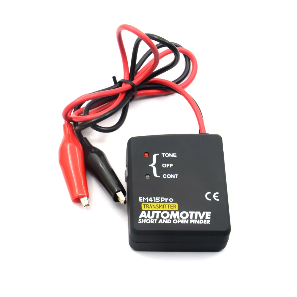
Transmitter Operating Modes
The transmitter includes selectable operating positions:
TONE Mode
Used to send a tracing signal through the selected wire or circuit. The receiver detects this signal and provides an audible indication.
OFF Mode
Turns off the transmitter when the test is complete.
CONT Mode
Used for supported continuity checks. The transmitter indicator provides information about the condition of the connected circuit.
Always disconnect the circuit from vehicle power before using continuity mode.
Typical Automotive Applications
The EM415PRO can assist with wiring diagnosis involving:
- Headlight and taillight wiring
- Turn-signal circuits
- Horn wiring
- Power-window circuits
- Central-locking wiring
- Fuel-pump wiring
- Cooling-fan circuits
- Trailer wiring
- Audio and speaker wiring
- Alarm-system wiring
- Accessory installations
- Fuse and relay circuits
- Dashboard wiring
- Ground circuits
- Damaged or modified wiring harnesses
How to Trace a Wire
- Turn off the vehicle ignition.
- Consult the vehicle wiring diagram.
- Disconnect sensitive electronic components from the circuit.
- Set the transmitter switch to OFF.
- Connect the transmitter leads to the wire being traced according to the manual.
- Set the transmitter to TONE mode.
- Turn on the receiver.
- Press and hold the receiver TEST button.
- Adjust the receiver sensitivity.
- Move the flexible probe along the suspected cable route.
- Follow the area producing the strongest audible signal.
- Reduce sensitivity as you approach the target wire.
- Turn off both units after completing the test.
How to Locate an Open Circuit
- Disconnect the circuit from the vehicle power supply.
- Connect the transmitter to the required wire.
- Activate TONE mode.
- Begin tracing from the transmitter connection point.
- Move the receiver gradually along the complete cable route.
- Mark the area where the audible signal becomes weak or disappears.
- Inspect the wire, connector or splice around that location.
- Confirm the open circuit with a digital multimeter.
How to Locate a Short Circuit
- Disconnect sensitive control units and electronic components.
- Connect the transmitter according to the supplied instructions.
- Set the transmitter to TONE mode.
- Follow the affected wire using the receiver probe.
- Observe changes in the audible signal.
- Inspect the area where the signal stops or changes significantly.
- Confirm the short using resistance or continuity measurements.
- Repair the wiring according to the vehicle manufacturer’s procedure.
Power Supply
The transmitter and receiver operate using replaceable batteries. Battery inclusion may vary according to shipping rules and seller package.
Weak batteries can reduce signal strength and receiver sensitivity. Replace the batteries if the signal becomes unstable or difficult to detect.
Package Contents
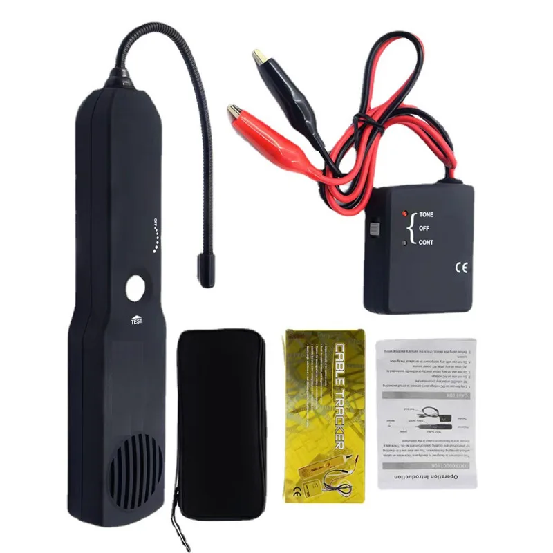
Based on the available product package, the kit includes:
- EM415PRO handheld receiver
- Flexible receiver probe
- Signal transmitter
- Red connection lead with alligator clip
- Black connection lead with alligator clip
- Carrying pouch
- User manual
- Retail packaging, depending on supplier
Batteries may not be included.
Important Limitations
- The device does not measure current leakage in amperes.
- It is not a parasitic battery-drain meter.
- It does not display voltage, resistance or current values.
- A multimeter may still be required to confirm the fault.
- The device is not an OBD2 diagnostic scanner.
- It does not read or clear vehicle fault codes.
- It does not test CAN Bus data communication.
- Results can be affected by nearby wires, shielding and electrical interference.
- The correct wiring diagram should be used whenever possible.
Critical Safety Warnings
- Use on DC circuits only.
- Never connect the device to a circuit exceeding 42V DC.
- Do not use the device on AC voltage.
- Do not connect it to household electricity.
- Do not use it on circuits connected directly or indirectly to an AC supply.
- Do not use it on ignition coils, spark-plug wiring or other high-voltage ignition components.
- Disconnect airbags, electronic control modules and other surge-sensitive components before testing related wiring.
- Turn off circuit power before using continuity mode.
- Follow the vehicle manufacturer’s disconnection procedures.
- Restore every disconnected component after completing the test.
- Incorrect connection can damage the tool or vehicle electronics.

Reviews
There are no reviews yet.