
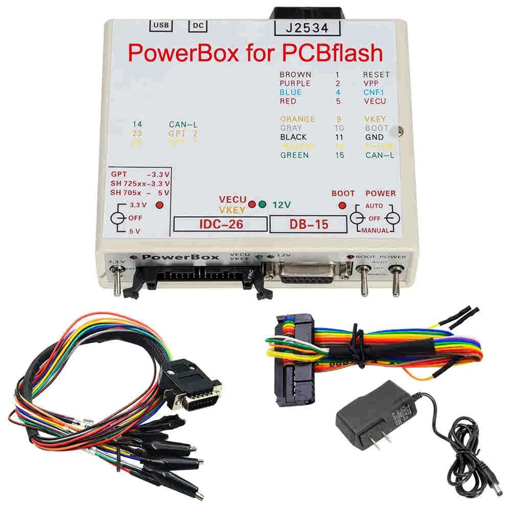
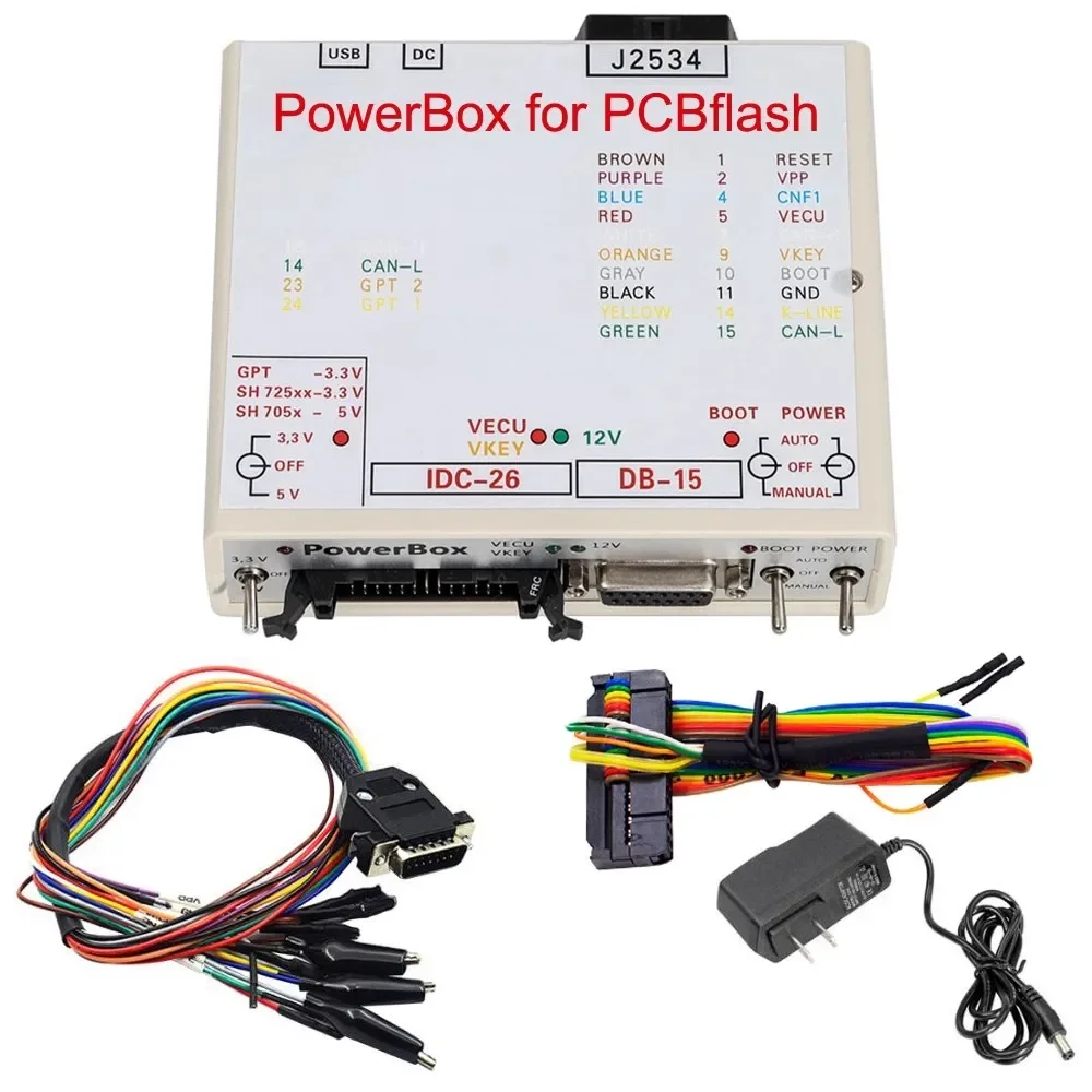
PowerBox ECU Programmer for KTMFlash and J2534
The PowerBox ECU Programmer is a professional connection and power-control adapter designed for ECU reading, writing and bench programming with compatible KTMFlash, KTMbench and J2534 equipment.
It provides flexible ECU power, signal and boot-mode control through multiple connectors. The integrated switches allow technicians to select manual or automatic operation according to the ECU, processor and loading software being used.
Main Features
- Designed for professional ECU bench programming
- Compatible with supported KTMFlash and KTMbench operations
- Connects to compatible J2534 interfaces through OBD-II
- Supports automatic control through BOOT-OEM12 and L-Line
- Manual and automatic ECU power control
- BOOT, RESET and CNF1 signal management
- Selectable 3.3V or 5V operation
- Supports Renesas and Tricore GPT applications
- Integrated USB-to-UART functionality
- Built-in current-limiting resistors for important signal lines
- Multiple connectors for flexible ECU connections
- LED indicators for power, voltage and control signals
Automatic Mode Support
The PowerBox can operate automatically with compatible loading software using:
- BOOT-OEM12: OBD-II pin 12
- L-Line: OBD-II pin 15
Actual automatic-mode support depends on the connected interface, ECU, programming software and selected protocol.
Built-In Signal Protection
The tool includes current-limiting resistors on the following control lines:
- RESET: 510Ω
- BOOT: 510Ω
- CNF1: 220Ω
These resistors provide additional signal-line protection during supported programming operations. They do not protect against incorrect wiring, reversed polarity or unsuitable voltage.
Available Connections
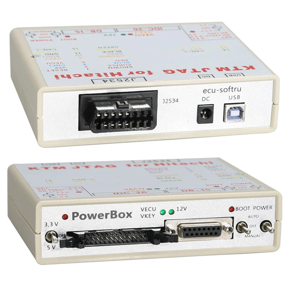
USB
The USB connector is used for:
- Connecting the PowerBox to a computer
- Using the integrated USB-to-UART converter
- Updating the PowerBox software
- Supported Renesas CPU programming operations
For Renesas CPU flashing, the Flash Development Toolkit may be required, depending on the processor and procedure.
DC Power Input
The DC connector powers the internal PowerBox circuit and the connected ECU.
A stable, regulated 12V power supply with sufficient current capacity is strongly recommended. Some ECUs contain high-voltage converters that may draw considerable current during startup. An unsuitable power supply may activate protection, interrupt programming or cause equipment damage.
J2534 OBD-II Female Connector
This connector is used to connect a compatible J2534 interface through its OBD-II connection.
Software and ECU support depend on the J2534 device, driver, programming application and activated software modules.
DB-15 Connector
The DB-15 connector is designed for connection to the ECU’s main connector.
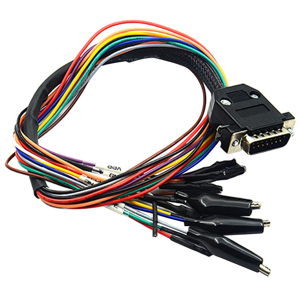
Compatible cables such as 14P600KT02, 14P600KT03, or equivalent correctly wired cables may be used.
IDC-26 Connector
The IDC-26 connector allows direct connection to the ECU circuit board or connection through a compatible adapter and programming head.
For supported Tricore GPT operations, cable 14P600KT06 or an equivalent correctly wired cable is recommended.
Control Switches
The PowerBox includes three main control switches:
POWER Switch
Controls the ECU power supply and provides three operating modes:
- OFF: Removes power and control signals from the IDC-26 and DB-15 connectors.
- MANUAL: Supplies power to the VECU and VKEY terminals and activates the required control outputs manually.
- AUTO: Allows compatible loading software to control ECU power through the L-Line signal on OBD-II pin 15.
BOOT Switch
Controls the BOOT, RESET and CNF1 signals at 3.3V:
- OFF: Removes the control signals from the DB-15 connector.
- MANUAL: Pulls RESET and BOOT to signal ground and CNF1 to +3.3V.
- AUTO: Allows compatible loading software to control BOOT, RESET and CNF1 simultaneously through OEM12 on OBD-II pin 12.
GPT Voltage Switch
This switch is intended for supported Renesas and Tricore GPT processors.
- Use 5V when working with supported SH705x processors.
- Use 3.3V for other supported applications unless the official wiring instructions specify otherwise.
Always confirm the correct voltage before connecting or powering the ECU.
LED Indicators
The PowerBox includes several status indicators:
- 5V/3.3V LED: Displays the selected operating voltage
- VECU/VKEY LED: Indicates voltage supplied to VECU and VKEY
- 12V LED: Indicates the main power-supply voltage
- BOOT LED: Indicates voltage on the CNF1 output and may operate during both input and output activity
Supported Operations
Depending on the ECU, processor, software and activated module, the PowerBox may assist with:
- ECU reading and writing
- Bench programming
- Boot-mode operations
- ECU data backup and restoration
- Supported ECU cloning procedures
- Renesas processor programming
- Tricore GPT connections
- Password-reading procedures
- ECU repair and replacement work
Package Includes
- 1 × PowerBox for KTMFlash
- 1 × Color wiring diagram
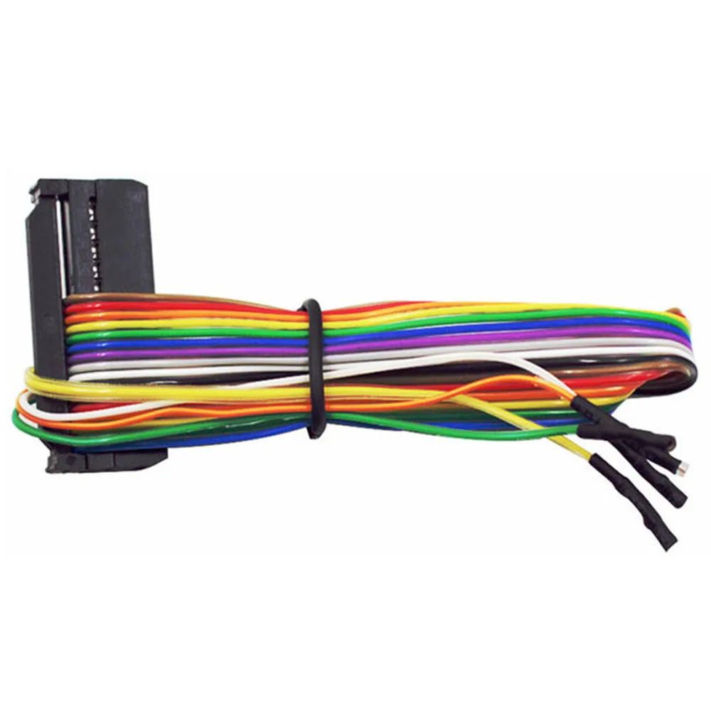
- 1 × GPT color cable
- 1 × Power charger plug
Only the items listed above are included unless additional cables or adapters are clearly shown and confirmed in the selected package.
Requirements
Additional equipment may be required:
- Compatible KTMFlash, KTMbench or J2534 interface
- Appropriate programming software
- Activated software modules
- Windows computer
- Stable regulated 12V power supply
- Correct ECU wiring diagram and pinout
- Required DB-15, IDC-26 or ECU-specific cables
Important Compatibility Notice
The PowerBox is a connection and power-control adapter, not a standalone ECU programmer. ECU coverage and available read/write methods depend on the connected programming interface, software, activated modules, ECU type and processor.
KTMbench, KTMFlash and other programming solutions do not provide identical coverage. Some ECUs, transmission control units and memory chips may require another tool, a specific software module or ECU disassembly.
Always confirm ECU, TCU, processor and software compatibility before purchasing or connecting the tool.
Safety Notice
Incorrect voltage, polarity, pinout or connection method may damage the ECU, PowerBox, J2534 interface or computer. Always use the official wiring diagram and a regulated power supply. This product is intended for trained automotive electronics and ECU-programming technicians.

Reviews
There are no reviews yet.